Park Assist Simulation Project Report
Introduction
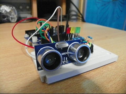
This project involves the use of an Arduino board to measure distances using two ultrasonic sensors and display the results on an LCD screen. The project utilizes two ultrasonic sensors—one facing the rear (Rear) and the other facing the front (Front) of an object. The system measures the distances to objects in both directions and provides real-time feedback on an LCD display, allowing users to monitor the surroundings of a vehicle or object. This project is valuable for applications such as parking assistance systems and obstacle detection.
In our fast-paced world, the Arduino Ultrasonic Distance Measurement project plays a vital role. It tackles the critical tasks of precise distance measurement and obstacle detection, with applications spanning automotive safety to robotics. This project not only showcases the practical application of ultrasonic sensors and microcontroller programming but also addresses real-world needs. By providing real-time distance feedback, it contributes to the development of intelligent systems, paving the way for safer and more efficient transportation and automation solutions. This project is a valuable stepping stone for innovation and problem-solving in our interconnected world.
Components
Arduino Uno R3
LCD 16 x 2
Ultrasonic Distance Sensor
330 Ω Resistor
Project Operation :
Sensors and Connections
The project utilizes two ultrasonic sensors and an LCD display. The sensors are HC-SR04 ultrasonic distance sensors, which have both trigger and echo pins. The connections are as follows:
LCD Connections: The LCD is connected using the LiquidCrystal library to control it. The specific pin connections for the LCD are as follows:
RS (Register Select) - Pin 10
E (Enable) - Pin 9
D4, D5, D6, D7 (Data pins) - Pins 8, 7, 6, 5
The LCD is initialized with a 16x2 configuration but can be modified for other LCD sizes.
Rear Ultrasonic Sensor (Rear Sensor):
Trigger Pin (RtrigPin) - Pin 12
Echo Pin (RechoPin) - Pin 11
Front Ultrasonic Sensor (Front Sensor):
Trigger Pin (FtrigPin) - Pin 4
Echo Pin (FechoPin) - Pin 3
Distance Measurement and Display
In the loop() function, the project operates as follows:
For each sensor (rear and front), it triggers an ultrasonic pulse by setting the respective trigger pin high for a short duration and then low.
The time it takes for the pulse to return (echo) is measured using the pulseIn() function.
The distance to the detected object is calculated based on the time measured and the speed of sound.
The distance measurements for both sensors are printed to the serial monitor for debugging purposes.
LCD Display
The LCD display provides real-time feedback based on the distance measurements:
If the rear distance is greater than the front distance, it displays "Watch your Rear!!!" on the LCD.
If the front distance is greater than the rear distance, it displays "Watch your Front!!!" on the LCD.
If both distances are equal, it displays "Perfect Park !!!" on the LCD.
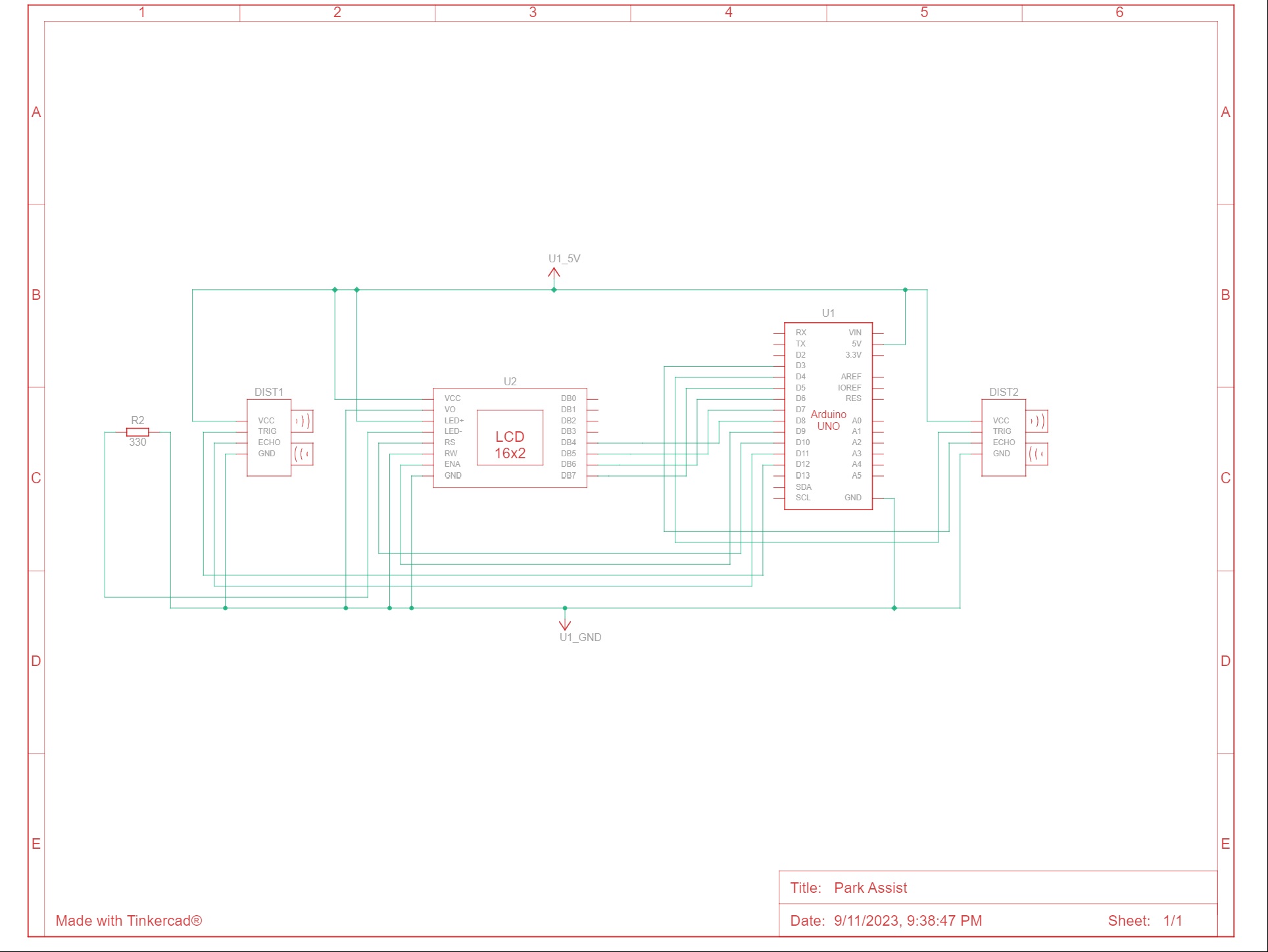
Circuit diagram
Code
#include
LiquidCrystal lcd = LiquidCrystal(10,9,8,7,6,5); // Create an LCD object. Parameters: (RS, E, D4, D5, D6, D7):
#define RtrigPin 12
#define RechoPin 11
#define FtrigPin 4
#define FechoPin 3
float Rtime, Rdistance, Ftime, Fdistance;
void setup()
{
lcd.begin(16, 2); // Specify the LCD's number of columns and rows. Change to (20, 4) for a 20x4 LCD
pinMode(RtrigPin, OUTPUT);
pinMode(RechoPin, INPUT);
pinMode(FtrigPin, OUTPUT);
pinMode(FechoPin, INPUT);
Serial.begin(9600);
}
void loop()
{
digitalWrite(RtrigPin, LOW);
delayMicroseconds(2);
digitalWrite(RtrigPin, HIGH);
delayMicroseconds(10);
digitalWrite(RtrigPin, LOW);
Rtime = pulseIn(RechoPin, HIGH);
Rdistance = (Rtime*.0343)/2;
// For Serial Monitor
Serial.print("R Distance:CM ");
Serial.println(Rdistance);
digitalWrite(FtrigPin, LOW);
delayMicroseconds(2);
digitalWrite(FtrigPin, HIGH);
delayMicroseconds(10);
digitalWrite(FtrigPin, LOW);
Ftime = pulseIn(FechoPin, HIGH);
Fdistance = (Ftime*.0343)/2;
// For Serial Monitor
Serial.print("F Distance:CM ");
Serial.println(Fdistance);
// For LCD Display
if (Rdistance > Fdistance)
{
lcd.setCursor(3,0);
lcd.print("Watch your");
lcd.setCursor(4,1);
lcd.print("Front !!!");
}
else if (Rdistance < Fdistance)
{
lcd.setCursor(3,0);
lcd.print("Watch your");
lcd.setCursor(4,1);
lcd.print("Rear !!!");
}
else
{
lcd.setCursor(3,0);
lcd.print("Perfect");
lcd.setCursor(3,1);
lcd.print("Park !!!");
}
}
Conclusion :
This Arduino-based ultrasonic distance measurement project successfully demonstrates the use of two ultrasonic sensors for real-time distance measurement and feedback on an LCD display. It has applications in vehicle parking assistance and obstacle detection scenarios. The project emphasizes the integration of hardware components with software control, making it a valuable educational tool for learning about sensor interfacing and display technologies.
Future Enhancements :
As technology advances, the Arduino Ultrasonic Distance Measurement project can be further enhanced to expand its capabilities and applicability:
1. Multiple Sensor Integration: Incorporate additional ultrasonic sensors to expand the coverage area and provide more comprehensive distance measurements. This enhancement can be particularly useful in applications requiring 360-degree obstacle detection.
2. Obstacle Classification: Implement algorithms and sensor fusion techniques to classify obstacles based on their size or shape. This can be valuable for distinguishing between pedestrians, vehicles, and stationary objects.
3. Obstacle Tracking: Extend the project to enable continuous tracking of moving objects. This enhancement could find applications in robotics and automation where tracking objects in real-time is essential.
4. Wireless Communication: Integrate wireless communication modules (e.g., Bluetooth or Wi-Fi) to transmit distance data to external devices or systems. This would enable remote monitoring and control of the distance measurement system.
5. Data Logging and Analysis: Add data logging capabilities to store historical distance measurements. Analyzing this data can provide insights into traffic patterns, object movement, or environmental changes.
6. Calibration and Accuracy: Develop a calibration mechanism to enhance distance measurement accuracy. Calibrating the system based on environmental factors such as temperature and humidity can improve precision.
7. User Interface: Create a user-friendly graphical interface for configuring sensor settings, displaying distance data, and setting distance thresholds. This would enhance the user experience and make the project more accessible.
8. Integration with Autonomous Systems: Integrate the distance measurement system with autonomous vehicles or robots, allowing them to make real-time decisions based on the surrounding environment.
9. Machine Learning Integration: Explore the use of machine learning models for object recognition and advanced decision-making. Machine learning can improve the system's ability to interpret complex scenes.
10. Energy Efficiency: Optimize power management to extend the project's operational life, making it suitable for battery-powered applications.
These future enhancements would transform the Arduino Ultrasonic Distance Measurement project into a more versatile and advanced system capable of addressing a wider range of applications, from smart transportation to robotics and automation. The potential for innovation and problem-solving in this field is substantial, and these enhancements open doors to exciting possibilities.