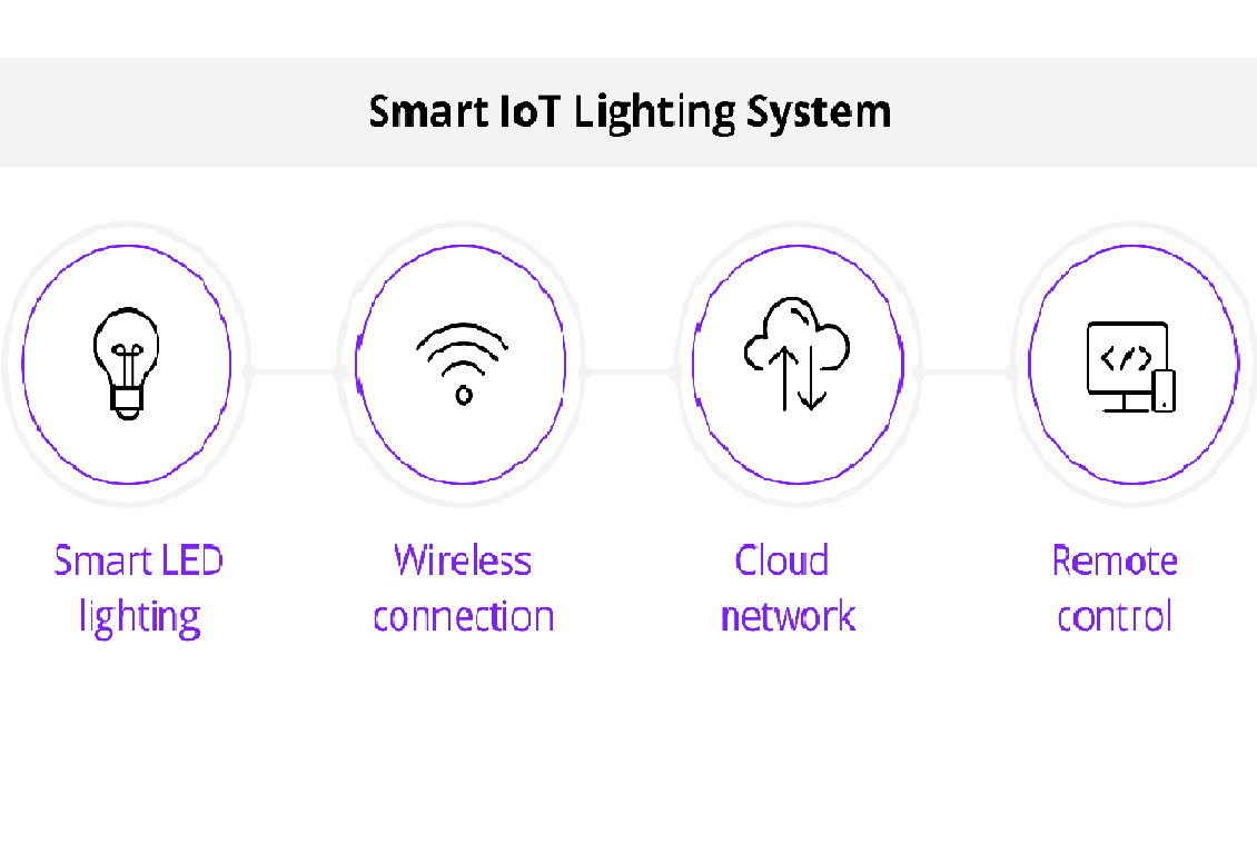
IoT Light Control System
Introduction
Create an IoT system that allows you to remotely control a light or LED using a web or mobile app. You'll be able to turn the light on and off from anywhere with an internet connection.
Components
Before you start building your Arduino-based drone, make sure you have the following components:
Arduino board (e.g., Arduino Uno)
Wi-Fi module (e.g., ESP8266 or ESP32)
Relay module (for controlling the light)
Breadboard and jumper wires
Light bulb or LED
Power source for Arduino (USB or battery)
Project Steps
1. Connect the Relay Module:
- Connect the VCC and GND pins of the relay module to the appropriate pins on the Arduino.
- Connect the IN1 (input) pin of the relay module to a digital pin on the Arduino (e.g., D2).
2. Connect the Light Source:
- Connect the live wire of the light bulb (or LED) to the Common (COM) terminal of the relay module.
- Connect the neutral wire of the light bulb to the neutral line.
3. Arduino Programming:
- Write Arduino code to control the relay module based on commands received from the WiFi module.
- Set up Wi-Fi connectivity using the Wi-Fi module.
4. Web/Mobile App Development:
- Develop a simple web or mobile app to send commands to the Arduino and control the light.
- Implement an on/off switch or button.
5. Remote Access:
- Ensure the web/mobile app is accessible from anywhere with an internet connection.
- Users can control the light remotely.
Circuit Connections:
1. Connect the Relay Module:
- Connect the VCC pin of the relay module to the 5V output on the Arduino.
- Connect the GND pin of the relay module to one of the GND pins on the Arduino.
- Connect the IN1 (input) pin of the relay module to a digital pin on the Arduino (e.g., D2).
2. Connect the Light Source:
- Connect one terminal of the light bulb (or LED) to the Common (COM) terminal of the relay module.
- Connect the other terminal of the light bulb to a suitable power source (e.g., the live wire from a wall socket).
- Connect the neutral wire from the power source to the neutral line.
3. Connect the Wi-Fi Module (ESP8266):
- Connect the VCC pin of the ESP8266 module to the 3.3V output on the Arduino.
- Connect the GND pin of the ESP8266 module to one of the GND pins on the Arduino.
- Connect the TX (transmit) pin of the ESP8266 module to a digital pin on the Arduino (e.g.,D10).
- Connect the RX (receive) pin of the ESP8266 module to a digital pin on the Arduino (e.g.,D11).
4. Power Supply:
- Power the Arduino with a USB cable or an external power source.
Note:
- Ensure that you connect the components as described above and use the correct pins on the Arduino.
- Double-check the pinout and wiring of your specific relay module and ESP8266 module if they differ.
- Additionally, you'll need to write Arduino code to control the relay module based on commands received from the Wi-Fi module and set up Wi-Fi connectivity. The specifics of the code may vary depending on your chosen Wi-Fi module and programming preferences.
Code
#include
// Replace with your network credentials
const char* ssid = "YourSSID";
const char* password = "YourPassword";
// Create an instance of the ESP8266WebServer class
ESP8266WebServer server(80);
// Define the GPIO pin connected to the relay module
const int relayPin = 2; // Change to the appropriate pin
void setup() {
Serial.begin(115200);
// Connect to Wi-Fi
WiFi.begin(ssid, password);
while (WiFi.status() != WL_CONNECTED) {
delay(1000);
Serial.println("Connecting to WiFi...");
}
Serial.println("Connected to WiFi");
// Set the relay pin as an OUTPUT
pinMode(relayPin, OUTPUT);
digitalWrite(relayPin, LOW); // Ensure the light is initially turned off
// Define the web server routes
server.on("/", HTTP_GET, handleRoot);
server.on("/on", HTTP_GET, handleOn);
server.on("/off", HTTP_GET, handleOff);
// Start the server
server.begin();
}
void loop() {
// Handle incoming client requests
server.handleClient();
}
// Handle root URL (main page)
void handleRoot() {
String html = "
";html += "
IoT Light Control
";html += "
";html += "
";html += "";
server.send(200, "text/html", html);
}
// Handle "Turn On" request
void handleOn() {
digitalWrite(relayPin, HIGH); // Turn the light on
server.send(200, "text/plain", "Light turned on");
}
// Handle "Turn Off" request
void handleOff() {
digitalWrite(relayPin, LOW); // Turn the light off
server.send(200, "text/plain", "Light turned off");
}
Before uploading this code to your Arduino board, make sure to:
1. Replace `"YourSSID"` and `"YourPassword"` with your Wi-Fi network credentials.
2. Adjust the `relayPin` variable to the appropriate GPIO pin connected to the relay module.
Once uploaded, open the Arduino Serial Monitor to get the ESP8266's IP address. Then, enter this IP address into your web browser to access the web interface, where you can control the light by clicking "Turn On" and "Turn Off."
