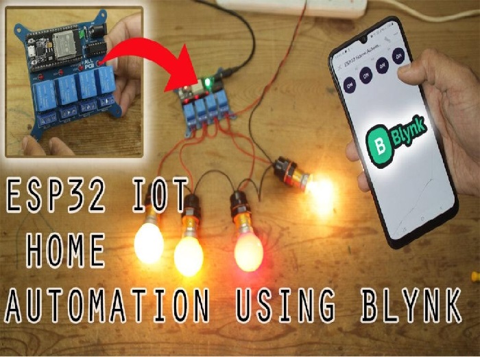
IOT based Home Automation System using ESP32
Introduction
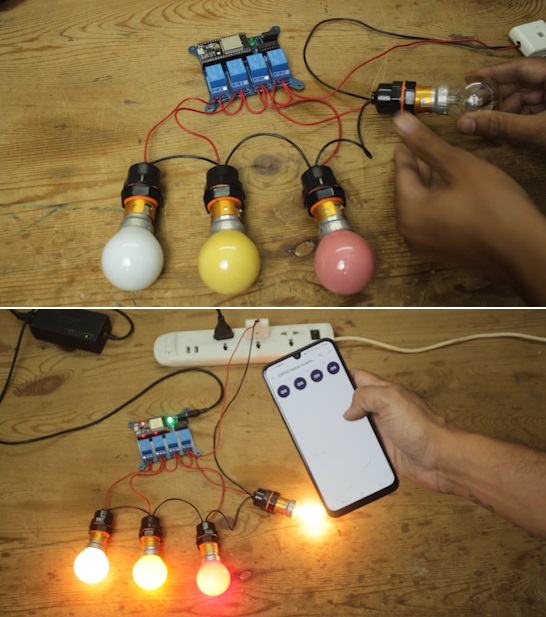
Hey there, in this project, we'll learn how to create a smart home system using an ESP32 and Blynk 2.0, which is a tool for Internet of Things (IoT) projects. Nowadays, IoT is a hot topic, and it's all about connecting things to the internet.
With this project, we're going to make it possible to control high-power devices in your home like lights, fans, and air conditioners from your phone or computer.
To make this project more professional, we'll design a printed circuit board (PCB) for it. You could try making it on a zero PCB (a homemade PCB), but I recommend going for a custom PCB because this project deals with high voltage, and homemade PCBs might have more chances of errors.
We're going to use Blynk's IoT Cloud as our platform to connect everything in this project. So, before we dive deeper into this project, let's first see what components we need to get started with our ESP32-based home automation project.
Components
Before you start building your Arduino-based drone, make sure you have the following components:
ESP32 DEV Board
Custom PCB
5V DC Relay HE JQC3FC
5MM DC Power Jack
16 Pin IC Base
ULN2003 IC
FR207 Diode
5mm Green LED
3mm Red LED
3Pin 5.08 pitch PCB terminal
220 ohm resistor
LM7805 T0252
Circuit Diagram
This is the drawing that shows how to make a smart home system with the ESP32. I picked the ESP32 because it can connect to the internet using build-in Wi-Fi module. We can use the internet to control things in our home, like turning things on and off using a service called Blynk IOT cloud.
To make things work, I used a special chip called ULN2003, which has seven little switches inside. The ESP32 sends signals to the ULN2003, and then the ULN2003 can turn things like a relay on or off. This is important because the ESP32 can only use 3 volts to control things, and a relay needs 5 volts. The ULN2003 helps with this.
I also used a tiny voltage regulator called LM7805 to make sure the ESP32 and the relay always get the right amount of power, which is 5 volts.
For safety, I added a diode called FR207 to protect the circuit from electrical accidents, and a green LED to show when the circuit has power. There's also a red LED for each relay. If a red LED is on, it means the relay is on, and if it's off, the relay is off.
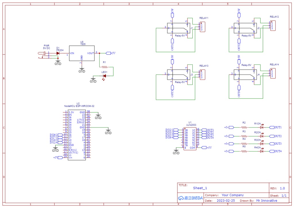
Circuit drawing of ESP32 IOT based Home Automation Project
Custom PCB
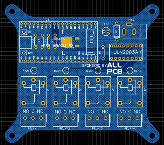
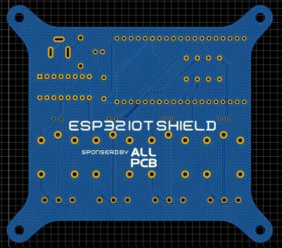
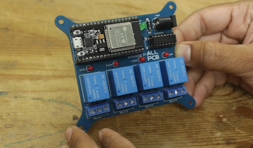
I've made the circuit board design based on the diagram above. As I mentioned before, this project deals with high voltage, and I don't want to take any chances. That's why I've created this PCB in a professional manner.
Below is the link of PCB and schematic (if require keep the link else delete)
https://oshwlab.com/sharmaz747/esp32-home-automation-shield
Preparing PCB
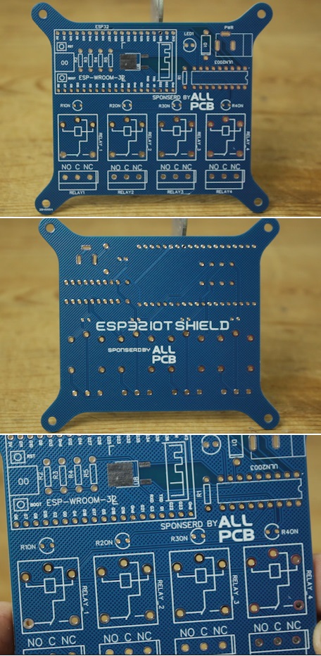
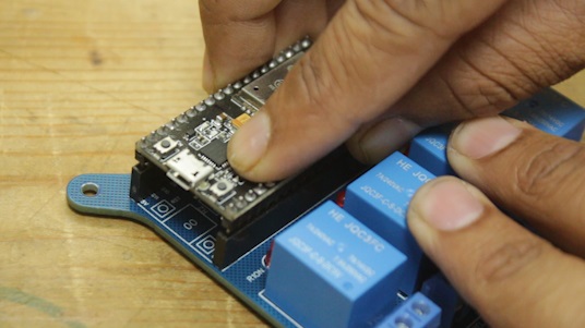
Time to solder all the components on PCB.
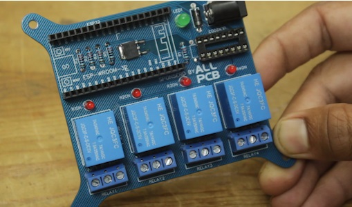
Once we finish soldering, we'll put the ESP WROOM 32 and the ULN2003 IC on it.
Now that our PCB is all set up, it's time to set up the software part. In this project, we're using the Blynk app to control when the relay turns on and off.
Blynk IOT setup for ESP32 based Home Automation Project
There are basically three steps to complete whole Blynk IOT setup
1.Configuring Blynk web setup (getting firmware key & setting widget)
2.Uploading code to ESP32 (uploading code using Arduino IDE)
3.Configuring Blynk mobile app (Wi-Fi credential and app widget)
Configuring Blynk web setup
As of now, our circuit board is all set up with all the parts soldered in place, including the ESP32 board. Now, it's time to create an IoT dashboard using Blynk and set up the Blynk mobile app. This will allow us to control the device connected to the circuit board from anywhere through the internet.
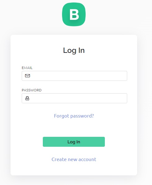
To get started, you'll need to go to the Blynk IoT Cloud login page. You'll find a page that looks like this, where you can either log in or sign up for an account on the Blynk IoT Cloud. It's a simple and straightforward process.
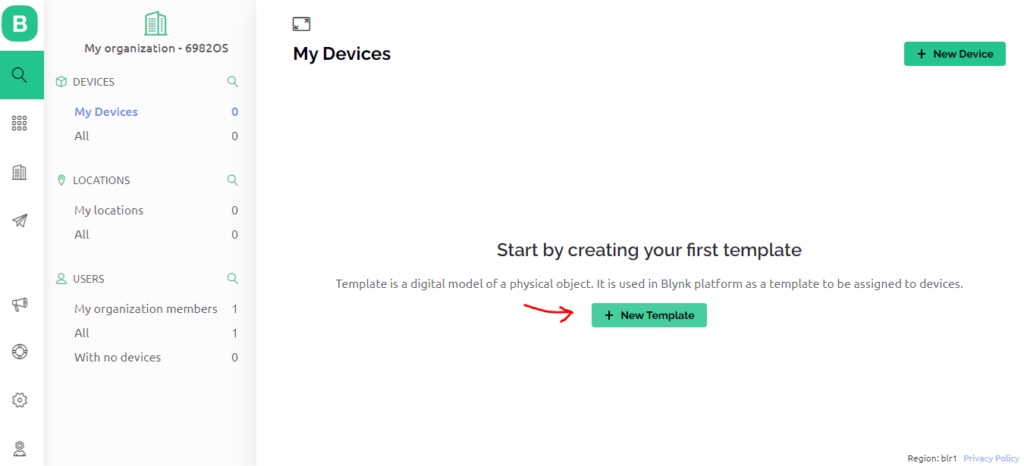
Once you've logged in successfully, you'll see a starting page like this. To begin, simply click on the "+New Template" option.
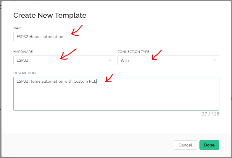
When you click on "+New Template," you'll be prompted to provide some basic details. These include the template's name, the type of hardware you're using (in this case, ESP32), the connection method (WIFI), and a brief description. Finally, just click "Done" to finish.
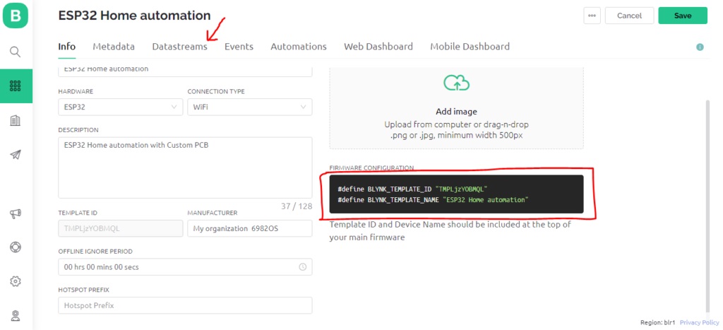
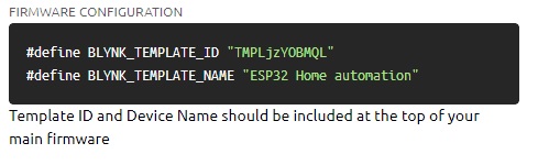
Once we've clicked "done," our template is ready. The first thing we need to do is either write down or copy and paste the two lines of code that are highlighted in the red box. We'll need these lines when we upload the code to the ESP32 Board. Afterward, click on "Datastreams."
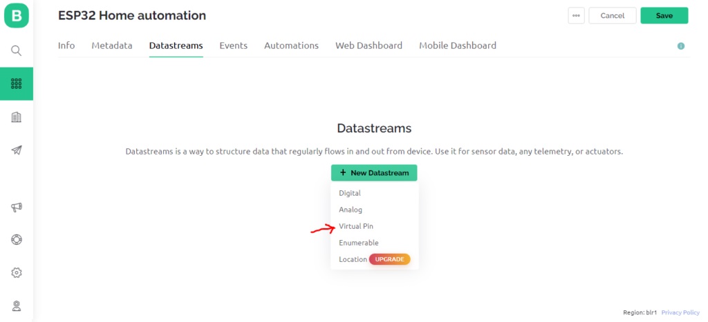
Next, press the "+New Datastream" button and choose the "Virtual Pin" option.
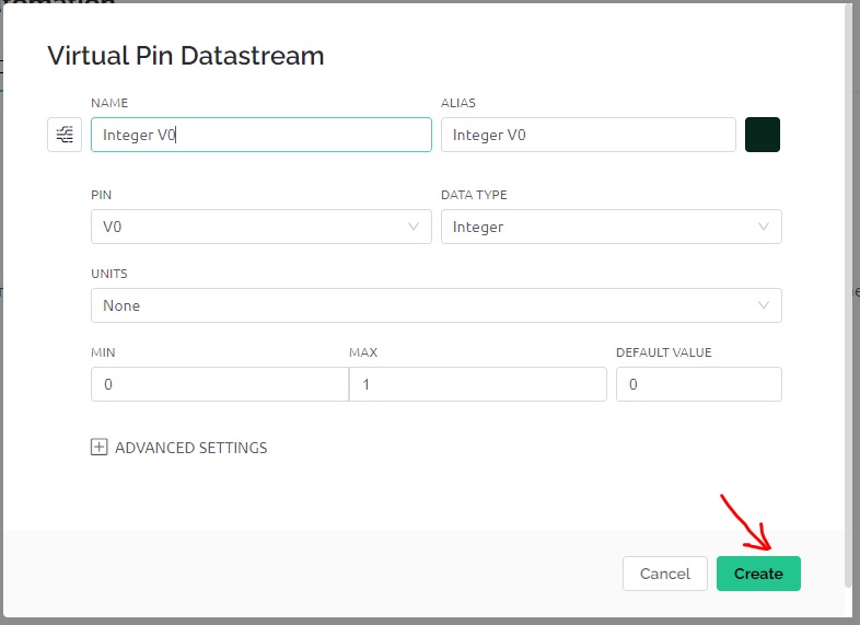
When you click on the virtual pin, a window like this will appear where you can set up the virtual pin. Since we're using a relay to switch things on and off, choose "Integer" as the data type.
MIN & MAX Value will 0 & 1
DEFAULT VALUE will be 0
Once you've done this, click on "Create," and your virtual pin will be ready to use.
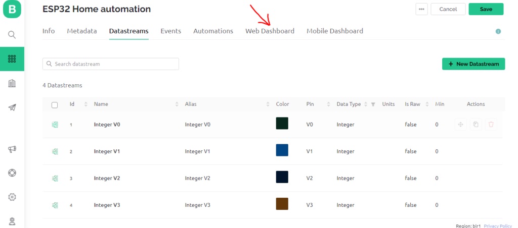
Similarly, we've made four virtual pins because we have four relays to control. Now, it's time to create a dashboard on the web where we can control these relays on the PCB. Just click on the web dashboard.
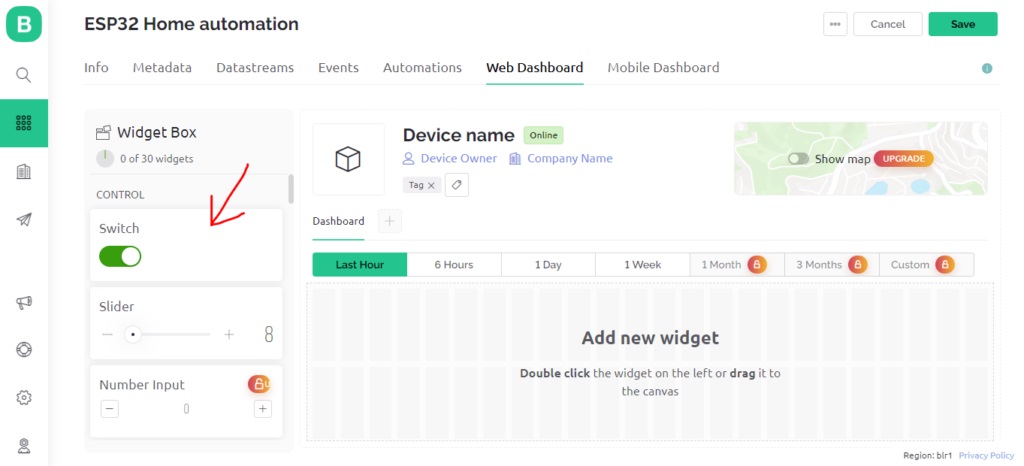
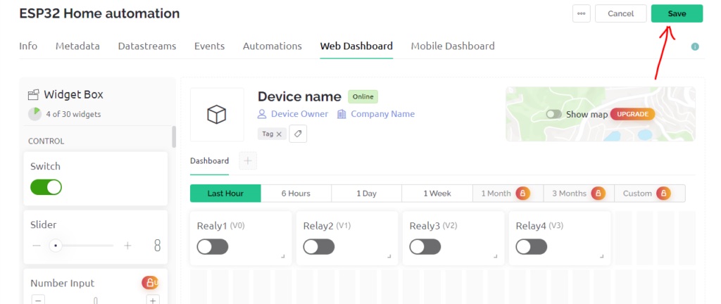
In the dashboard, you should grab the Switch widget from the left side and move it over to the right side. We'll need four of these switches.
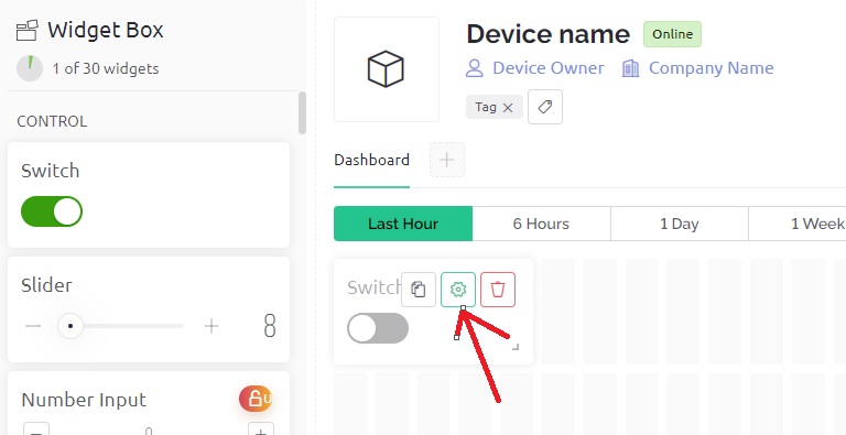
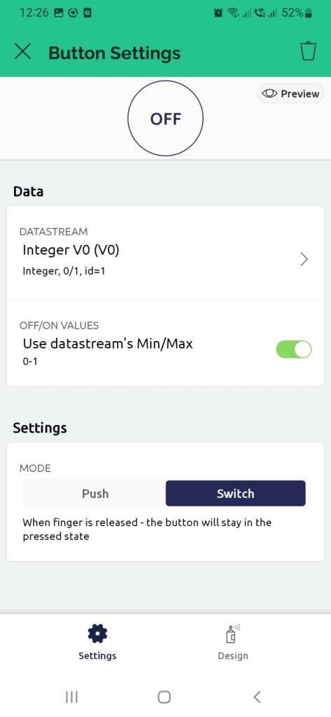
Once you've added the Switch widget, you'll need to set it up to work with the virtual pins you created earlier. To do this, click on the settings icon on the widget.
I named the first switch "Relay 1" because it controls relay 1. In the Datastream option, I picked "V0 virtual pin" for this switch. Without changing any other settings, just press the "save" button.
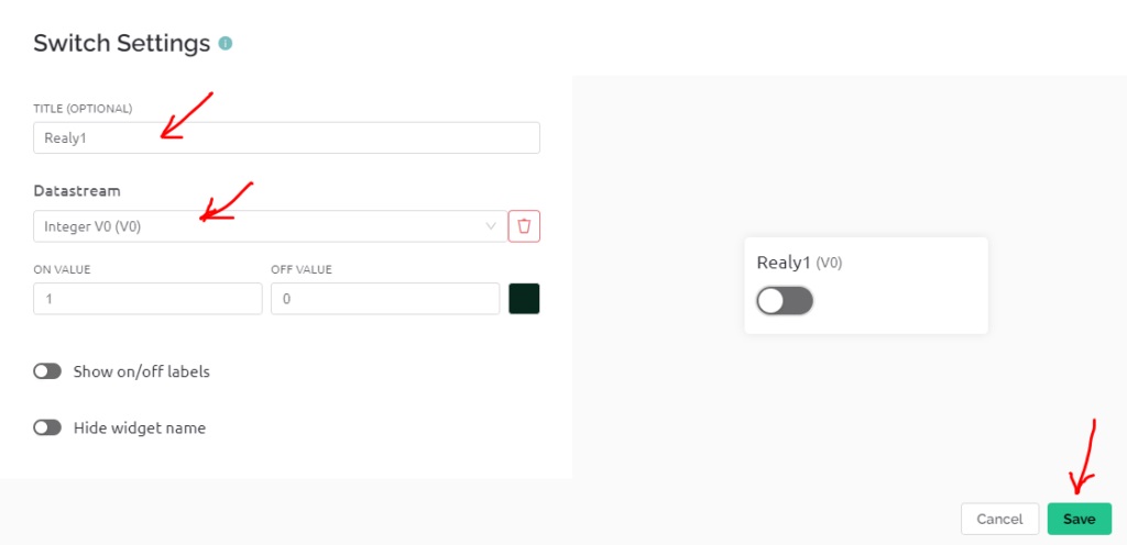
I've also made 4 switches that match each relay on our circuit board. Once you finish this step, click "Save." Our web dashboard setup is done, but we still have two more steps to go:
1.Uploading code to the ESP32.
2.Setting up the Blynk mobile app (we'll handle the Wi-Fi credentials here).
Now, let's move on to uploading the code to the ESP32. Don't close the Blynk window; instead, open the Arduino IDE.
Uploading code to ESP32
First, we need to install a Blynk library before we can proceed. You can get the library by downloading it from the following link:
[Link to Blynk library] (https://github.com/blynkkk/blynk-library)
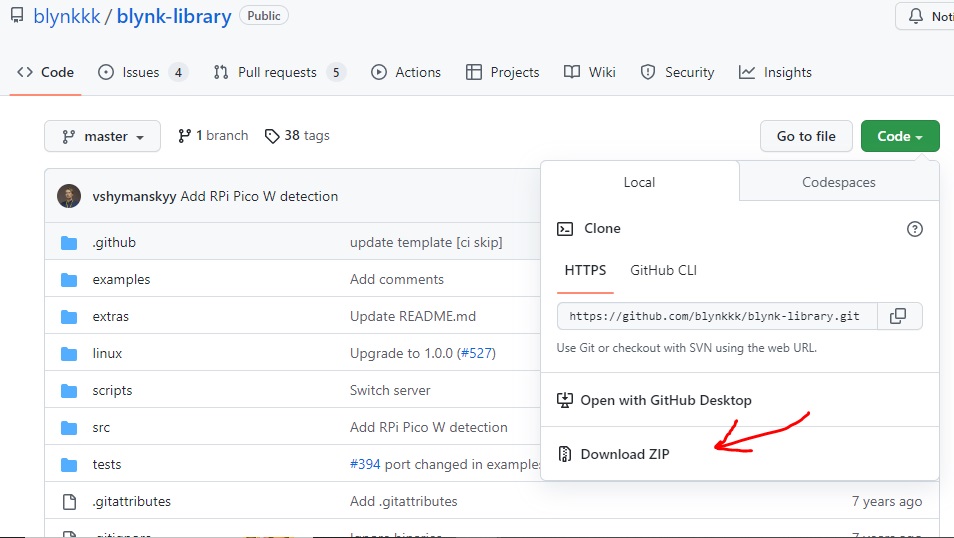
Once you've downloaded the zip file, follow these simple steps:
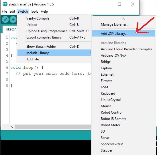
1.Open the Arduino IDE.
2.Go to the "Sketch" menu.
3.Click on "Include Library."
4.Then, choose "Add .ZIP Library."
Next, find the library you downloaded in zip format and finish installing it. Congratulations! You've now successfully added the Blynk library to your Arduino IDE.
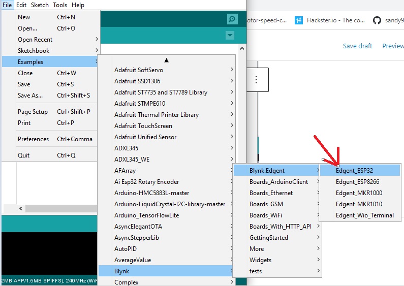
Next, go to the "File" menu, click on "Example," and search for "Blynk." Now, select "Blynk.Edgent," and finally, click on "Edgent_ESP32."
Now that we have the basic code open, we should add a few lines to customize it according to our needs. Here's the finished code for our project that controls four relays.
#define BLYNK_TEMPLATE_ID "TMPLjzYOBMQL"
#define BLYNK_TEMPLATE_NAME "ESP32 Home automation"
#define BLYNK_FIRMWARE_VERSION "0.1.0"
#define BLYNK_PRINT Serial
//#define BLYNK_DEBUG
#define APP_DEBUG
// Uncomment your board, or configure a custom board in Settings.h
//#define USE_ESP32_DEV_MODULE
//#define USE_ESP32C3_DEV_MODULE
//#define USE_ESP32S2_DEV_KIT
//#define USE_WROVER_BOARD
//#define USE_TTGO_T7
//#define USE_TTGO_T_OI
#include "BlynkEdgent.h"
BLYNK_WRITE(V0){
int pinValue = param.asInt();
digitalWrite(27,pinValue);
}
BLYNK_WRITE(V1){
int pinValue = param.asInt();
digitalWrite(26,pinValue);
}
BLYNK_WRITE(V2){
int pinValue = param.asInt();
digitalWrite(14,pinValue);
}
BLYNK_WRITE(V3){
int pinValue = param.asInt();
digitalWrite(12,pinValue);
}
void setup()
{
pinMode(27,OUTPUT);
pinMode(26,OUTPUT);
pinMode(14,OUTPUT);
pinMode(12,OUTPUT);
Serial.begin(115200);
delay(100);
BlynkEdgent.begin();
}
void loop() {
BlynkEdgent.run();
}
Explanation of above code:
#define BLYNK_TEMPLATE_ID "TMPLjzYOBMQL"
#define BLYNK_TEMPLATE_NAME "ESP32 Home automation"
You need to replace these initial two lines of code with the ones you copied and pasted earlier when setting up Blynk IoT on the web.
We made a setup for our four virtual pins, and each one controls a separate relay. In this setup, we specify which pin is connected to each relay.
BLYNK_WRITE(V0){
int pinValue = param.asInt();
digitalWrite(27,pinValue);
}
BLYNK_WRITE(V1){
int pinValue = param.asInt();
digitalWrite(26,pinValue);
}
BLYNK_WRITE(V2){
int pinValue = param.asInt();
digitalWrite(14,pinValue);
}
BLYNK_WRITE(V3){
int pinValue = param.asInt();
digitalWrite(12,pinValue);
}
Finally, we set up the pinMode in the "Void setup" function.
void setup()
{
pinMode(27,OUTPUT);
pinMode(26,OUTPUT);
pinMode(14,OUTPUT);
pinMode(12,OUTPUT);
Serial.begin(115200);
delay(100);
BlynkEdgent.begin();
}
After you finish this step, you can upload the code to the ESP32. Make sure you've selected the right board and port before uploading.
If you're unsure about how to put code onto your ESP32 using the Arduino IDE, you can learn by reading this article: "How to program ESP32 using Arduino IDE" at this link: [ https://electricdiylab.com/how-to-program-esp32-using-arduino-ide-wroom-esp32/ ].
We've finished two steps so far, and now, let's go on to the third and last step.
Configuring Blynk mobile app
To make your mobile phone control the relay and share your Wi-Fi info with the ESP32, you need to set up the Blynk mobile app.
Start by downloading the Blynk app and logging in with the same ID you used for Blynk's web IoT cloud service.
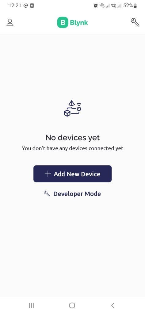
Once you're logged in, simply press the "Add New Device" button.
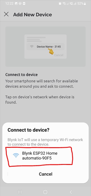
If you want to use the "connect nearby system" option, place your ESP32 close to your mobile phone. The mobile app will then find the ESP32 automatically. Next, select the available Wi-Fi device to connect to. Finally, pick the Wi-Fi router you want to connect to.
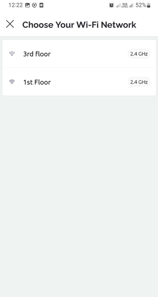
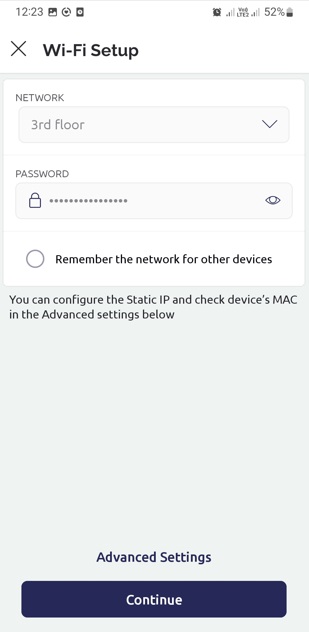
To get your ESP32 ready to connect to your home Wi-Fi router, you need to type in your Wi-Fi router's password like this.
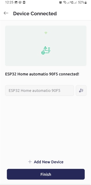
Now that we're connected to the device, go ahead and click "Finish."
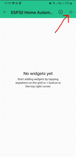
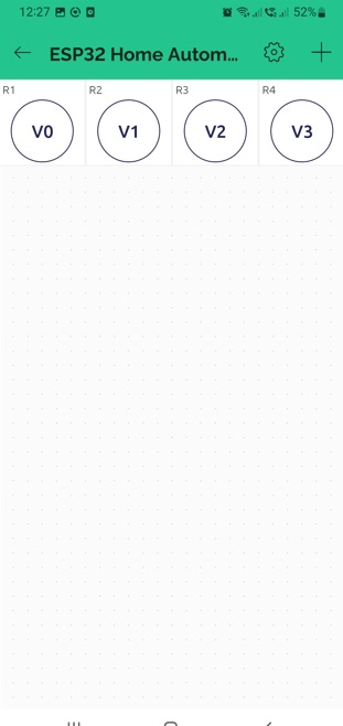
Now, we need to add a Switch widget, just like what we did for the web. To do this, click on the plus (+) icon and choose the Switch option.
Now, I've added four switch widgets for the four relays, and I've assigned them to virtual pins V0, V1, V2, and V3. The crucial step is to select the "MODE" option in the switch settings. If you don't do this, the relay will turn on when you click the widget, and it will only turn off when you release the switch.
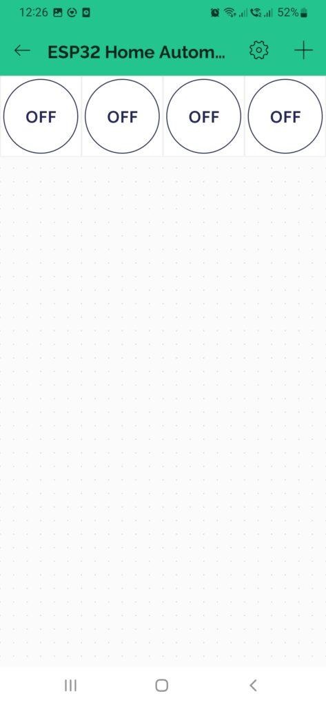
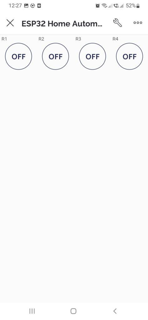
Our ESP32 IoT home automation project is all set! To control the relay and turn things on and off, simply click the widget. After completing all the required steps, you can connect your actual devices to the PCB and control them using your mobile phone or computer.