Arduino IoT Plant Monitoring System
Introduction
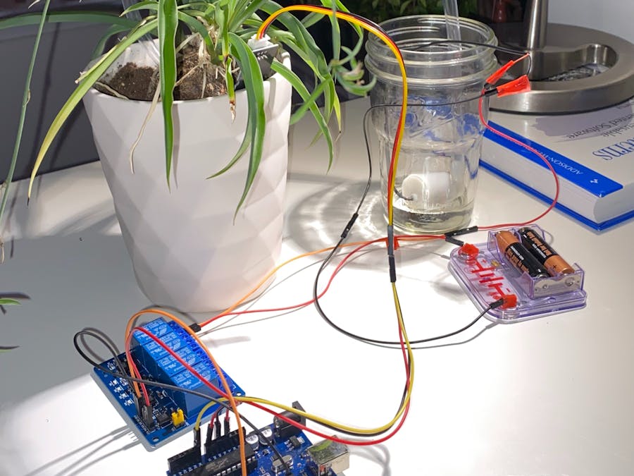
The Arduino IoT Plant Monitoring System is a project designed to monitor and control the environment of your plants using various sensors and the Blynk IoT platform. This system includes the following features:
- Monitoring temperature and humidity with a DHT11 sensor.
- Measuring soil moisture with a soil moisture sensor.
- Detecting motion using a PIR (Passive Infrared) motion sensor.
- Controlling a relay to turn on/off a connected device (e.g., a water pump or light).
- User interface via the Blynk mobile app to visualize data and control the system remotely.
Components
Before you start building your Arduino-based drone, make sure you have the following components:
Arduino board (e.g., ESP8266)
DHT11 Temperature and Humidity Sensor
Soil Moisture Sensor
PIR (Passive Infrared) Motion Sensor
Relay module
Liquid Crystal Display (LCD) with I2C interface
Push button
Jumper wires
Breadboard (optional)
Pin Connections
- Relay: D3
- Button: D7
- Soil Moisture: A0
- PIR Motion Sensor: D5
- I2C SDA: D2
- I2C SCL: D1
- DHT11 Temperature Sensor: D4
Libraries Used
- [LiquidCrystal_I2C](https://github.com/fdebrabander/Arduino-LiquidCrystal-I2C-library): Used for interfacing with the I2C LCD.
- [ESP8266WiFi](https://github.com/esp8266/Arduino): Enables WiFi connectivity for the ESP8266 board.
- [BlynkSimpleEsp8266](https://github.com/blynkkk/blynk-library): Provides Blynk integration for IoT communication.
- [DHT](https://github.com/adafruit/DHT-sensor-library): A library for the DHT11 temperature and humidity sensor.
Setup
1. Connect the components following the specified pin connections.
2. Install the required libraries using the Arduino IDE.
3. Replace placeholders in the code (`auth`, `ssid`, `pass`) with your Blynk authentication token and WiFi credentials.
4. Upload the code to your Arduino board.
5. Ensure that the power source for the relay module and sensors is connected.
How It Works
1. The system initializes and establishes a connection to the Blynk server and sensors.
2. Temperature and humidity data are read from the DHT11 sensor and displayed on the LCD.
3. Soil moisture data is read from the soil moisture sensor and displayed on the LCD.
4. The PIR motion sensor detects motion and alerts the user via the Blynk app.
5. A physical push button allows manual control of the relay to turn a connected device on/off.
6. The Blynk app provides a user-friendly interface to monitor sensor data and control the relay remotely.
Blynk Mobile App Interface
1. Toggle Motion Detection: Use a button widget (V6) on the Blynk app to toggle motion detection on/off.
2. Toggle Relay: Use a button widget (V12) to control the relay's state.
3 Temperature Display: Sensor data (temperature and humidity) is displayed on value display widgets (V0 and V1).
4. Soil Moisture Display: Soil moisture data is displayed on a value display widget (V3).
5. Motion Alert: A LED widget (V5) indicates motion detection.
Arduino code
/* Connections
Relay. D3
Btn. D7
Soil. A0
PIR. D5
SDA. D2
SCL. D1
Temp. D4
*/
// Include the library files
#include
#define BLYNK_PRINT Serial
#include
#include
#include
// Initialize the LCD display
LiquidCrystal_I2C lcd(0x3F, 16, 2);
char auth[] = "YOUR_AUTH_TOKEN"; // Enter your Blynk Auth token
char ssid[] = "YOUR_WIFI_SSID"; // Enter your WIFI SSID
char pass[] = "YOUR_WIFI_PASSWORD"; // Enter your WIFI Password
DHT dht(D4, DHT11); // (DHT sensor pin, sensor type) D4 DHT11 Temperature Sensor
BlynkTimer timer;
// Define component pins
#define SOIL_SENSOR A0 // A0 Soil Moisture Sensor
#define PIR_SENSOR D5 // D5 PIR Motion Sensor
int pirToggleValue;
void checkPhysicalButton();
int relay1State = LOW;
int pushButton1State = HIGH;
#define RELAY_PIN_1 D3 // D3 Relay
#define PUSH_BUTTON_1 D7 // D7 Button
#define VPIN_BUTTON_1 V12
// Create variables for temperature and pressure
double temperature, pressure;
char status;
void setup() {
Serial.begin(9600);
lcd.begin();
lcd.backlight();
pinMode(PIR_SENSOR, INPUT);
pinMode(RELAY_PIN_1, OUTPUT);
digitalWrite(RELAY_PIN_1, LOW);
pinMode(PUSH_BUTTON_1, INPUT_PULLUP);
digitalWrite(RELAY_PIN_1, relay1State);
Blynk.begin(auth, ssid, pass, "blynk.cloud", 80);
dht.begin();
lcd.setCursor(0, 0);
lcd.print(" Initializing ");
for (int a = 5; a <= 10; a++) {
lcd.setCursor(a, 1);
lcd.print(".");
delay(500);
}
lcd.clear();
lcd.setCursor(11, 1);
lcd.print("W:OFF");
// Call the function
timer.setInterval(100L, readSoilMoisture);
timer.setInterval(100L, readDHT11Sensor);
timer.setInterval(500L, checkPhysicalButton);
}
// Get the DHT11 sensor values
void readDHT11Sensor() {
float humidity = dht.readHumidity();
float temp = dht.readTemperature();
if (isnan(humidity) || isnan(temp)) {
Serial.println("Failed to read from DHT sensor!");
return;
}
Blynk.virtualWrite(V0, temp);
Blynk.virtualWrite(V1, humidity);
lcd.setCursor(0, 0);
lcd.print("T:");
lcd.print(temp);
lcd.setCursor(8, 0);
lcd.print("H:");
lcd.print(humidity);
}
// Get the soil moisture values
void readSoilMoisture() {
int soilValue = analogRead(SOIL_SENSOR);
soilValue = map(soilValue, 0, 1024, 0, 100);
soilValue = (soilValue - 100) * -1;
Blynk.virtualWrite(V3, soilValue);
lcd.setCursor(0, 1);
lcd.print("S:");
lcd.print(soilValue);
lcd.print(" ");
}
// Get the PIR sensor values
void readPIRSensor() {
bool pirValue = digitalRead(PIR_SENSOR);
if (pirValue) {
Blynk.logEvent("pirMotion", "WARNING! Motion Detected!"); // Enter your Event Name
WidgetLED pirLED(V5);
pirLED.on();
} else {
WidgetLED pirLED(V5);
pirLED.off();
}
}
BLYNK_WRITE(V6) {
pirToggleValue = param.asInt();
}
BLYNK_CONNECTED() {
// Request the latest state from the server
Blynk.syncVirtual(VPIN_BUTTON_1);
}
BLYNK_WRITE(VPIN_BUTTON_1) {
relay1State = param.asInt();
digitalWrite(RELAY_PIN_1, relay1State);
}
void checkPhysicalButton() {
if (digitalRead(PUSH_BUTTON_1) == LOW) {
// pushButton1State is used to avoid sequential toggles
if (pushButton1State != LOW) {
// Toggle Relay state
relay1State = !relay1State;
digitalWrite(RELAY_PIN_1, relay1State);
// Update Button Widget
Blynk.virtualWrite(VPIN_BUTTON_1, relay1State);
}
pushButton1State = LOW;
} else {
pushButton1State = HIGH;
}
}
void loop() {
if (pirToggleValue == 1) {
lcd.setCursor(5, 1);
lcd.print("M:ON ");
readPIRSensor();
} else {
lcd.setCursor(5, 1);
lcd.print("M:OFF");
WidgetLED pirLED(V5);
pirLED.off();
}
if (relay1State == HIGH) {
lcd.setCursor(11, 1);
lcd.print("W:ON ");
} else if (relay1State == LOW) {
lcd.setCursor(11, 1);
lcd.print("W:OFF");
}
Blynk.run(); // Run the Blynk library
timer.run(); // Run the Blynk timer
}
Troubleshooting
- Ensure that the wiring connections are accurate and secure.
- Double-check the WiFi credentials and Blynk authentication token.
- Monitor the Arduino IDE's serial monitor for debugging information.
Future Enhancements
This project can be expanded and improved in several ways:
- Adding more sensors for additional environmental data (e.g., light intensity, pH level).
- Implementing automatic plant care routines (e.g., watering based on soil moisture).
- Integrating a camera for plant monitoring and image capture.
- Creating a mobile app with custom controls and data visualization.
Conclusion
The Arduino IoT Plant Monitoring System provides an accessible way to monitor and control your plants' environment using sensors and the Blynk platform. By enhancing and customizing this project, you can create a comprehensive plant care system tailored to your specific needs.